Introduction to PIC64GX Development: Setup, Tools, and First Project on Windows®
Introduction
In this guide, you will learn how to prepare your PIC64GX Curiosity Board, install the necessary software tools, and navigate the development workflow using Visual Studio Code (VS Code®) and Microchip’s Software Development Kit (SDK) extensions. By following the step-by-step instructions, you will gain hands-on experience with the platform and establish a solid foundation for further exploration and application development on PIC64GX devices.
This starting guide is designed to be accessible for beginners while providing enough detail for experienced developers to quickly get up and running with the PIC64GX series.
Useful References
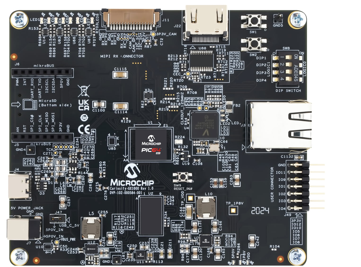
This application is developed for the CURIOSITY-PIC64GX1000-KIT-ES development platform. For platform-related documentation, see the following pages:
- PIC64GX1000 Curiosity Kit User Guide
- Curiosity PIC64GX1000 Kit Quickstart Guide
- PIC64GX1000 64-bit Microprocessor Data Sheet DS50003724
- PIC64GX1000 Curiosity Kit Schematics
Environment Setup
Hardware Setup
- CURIOSITY-PIC64GX1000-KIT-ES
- USB Type-C® cable
- Digital logic analyzer (not required, but useful for observing and analyzing signals)
Software Setup
Development Environment Configuration
This section describes the driver installation process, the VS Code extension installation process, and the workspace initializing process.
PIC64GX Extension Setup on VS Code
Open VS Code.
Now we need to install MPLAB PIC64GX SDK Extension on VS Code.
Open the extensions installer.
Search for "PIC64".
Select MPLAB PIC... extension.
Click on the Install button to install the extension.

You will see the following on your screen:

Install PIC64GX Drivers
Install the PIC64GX drivers.
To open the Windows Device Manager, right-click the Start button (or press Windows key + X), and then click Device Manager.
Confirm the Device Manager warning.
In the Device Manager window, click Other devices to expand the section.

Find and click on Other Devices, and double-click one of the devices named MCHP-Debug. The MCHP-Debug Properties window opens.
Click Change settings.
Click on Change settings.

On the Driver tab, click Update Driver. The Update Drivers - MCHP-Debug window opens.

Click Browse my computer for drivers.

Drivers are in the MPLAB® PIC64GX SDK Extension.
You will find the drivers under the extension folder. Example:
C:/Users/{USER}/.vscode/exenstions/microchip.pic64gx-sdk-extension-{VERSION}/PIC64GX_drivers
You can find the version of the extension that was installed in VS Code. Open the extension menu and look for the version.

Choose your drivers path and click Next.

Confirm the installation by clicking the Install button.

Confirm the driver update.

Repeat Steps 2 through 7 for each MCHP-Debug device in the Other devices section.
The Other devices section must now contain three USB Serial Port devices. Repeat Steps 2 through 6 for each USB Serial Port device.

To verify that the drivers have been installed, check for this view:

Initialize SDK
Open VS Code.
Press Ctrl + Shift + P to open the command menu, then type "PIC64" and find:

Specify the Python executable path to extension.

Choose a workspace where you would like to create the SDK.

Now we should wait for the SDK to be generated.
After a generation, you should see the following output:

Creating and Editing a Basic Project
Creating Project
Now, to continue, we need to create a project. To create the project, click on Extension on the left dock.

Click on the Create New SDK Project.
Put the name of your project into the Enter project name field.
The next step is to create a project folder in the SDK.
This is a path example for your project:
Then we should add the project's absolute path into the Enter project directory field.
Then click on Create Project and wait until the project is created. You will see the following output:
To understand if the project was generated successfully, we need to check:
Press Ctrl + Shift + E and expand your project folder; now you should have the hierarchy shown in the accompanying image:

Bare Metal Application Development
Now we can begin customizing u54_1.c.
Open the u54_1.c file located in:
Start modifying it.
This bare metal program runs on the PIC64GX platform and blinks a General Purpose Input/Output (GPIO) pin using direct hardware access:
- It enables the clock for the GPIO1 peripheral.
- Initializes GPIO1_LO and configures pin 2 as an output.
- In an infinite loop, it toggles the pin high and low every second using a delay loop.
2
3
4
5
6
7
8
9
10
11
12
13
14
15
16
17
18
19
20
21
22
23
24
25
26
27
28
29
30
31
#include "pic64gx_hal/mss_hal.h"
#include "mss_gpio/mss_gpio.h"
void delay(uint8_t seconds){
for (uint64_t i = 0; i < (seconds * 11000000U); ++i) {
__asm__("sll x0, x0, x0"); // Dummy instruction for delay
}
}
void u54_1(void)
{
// Enable clock for GPIO1 peripheral
(void)mss_config_clk_rst(MSS_PERIPH_GPIO1, (uint8_t) 1, PERIPHERAL_ON);
// Initialize GPIO1 lower half
MSS_GPIO_init(GPIO1_LO);
// Configure pin 2 as output
MSS_GPIO_config(GPIO1_LO, MSS_GPIO_2, MSS_GPIO_OUTPUT_MODE);
// Blink loop
while (1u)
{
delay(1);
MSS_GPIO_set_output(GPIO1_LO, MSS_GPIO_2, 1u); // LED ON
delay(1);
MSS_GPIO_set_output(GPIO1_LO, MSS_GPIO_2, 0u); // LED OFF
}
}
| Line 1 | Includes standard integer types like uint8_t, uint64_t |
| Line 2-3 | Includes Microchip’s hardware abstraction layer (HAL) and GPIO driver headers |
| Line 5-9 | Defines a crude delay loop using a dummy RISC-V instruction (sll x0, x0, x0) to waste CPU cycles Multiplies seconds by a constant to approximate timing |
| Line 11 | Entry point for core U54_1 (one of the RISC-V application cores on PIC64GX) |
| Line 14 | Enables the clock and resets the GPIO1 peripheral |
| Line 17 | Initializes the lower half of GPIO1 (pins 0–15) |
| Line 20 | Configures pin 2 on GPIO1_LO as an output |
| Line 23 | Infinite loop to keep blinking |
| Line 25-26 | Waits 1 second, then sets pin 2 high (LED ON) |
| Line 27-28 | Waits another second, then sets pin 2 low (LED OFF) |
Now we need to add GPIO drivers to our project.
Open the:
C:\...\{SDK_WORKSPACE}\{YOUR_PROJECT_NAME}\src\application\proj.conf file and append CONFIG_MSS_GPIO=y.
Building Project
To build the project, open the Extension menu.

Click on Build SDK Project.
In the Choose a board field, add your board directory.
Pass your project directory to Project directory:
Click on the Build button.
Wait until the project builds. You should see this message:
Terminal will be reused by tasks, press any key to close it.

Running Project
Open Run and Debug (Ctrl + Shift + D).

Open the drop-down menu and select debug-PIC64GX configuration.

Click on the green start button.
You will see this pop-up. Add your .elf file path (typically, it is build\{YOUR_PROJECT_NAME}.elf) and press Enter. 
Select the microchip_pic64gx_curiosity option.

When debugging has started, you should see these buttons:
They allow you to continue, step into or over that line, and restart and end the debug. From left to right:
- Continue execution and stop on the next breakpoint.
- Step over the current point.
- Step into the current point.
- Step out current point.
- Restart the debug session and reset the device.
- Stop debug session.
Now the debug is running. To add a breakpoint, open your source files (e.g., C:\...\{SDK_WORKSPACE}\{YOUR_PROJECT_NAME}\src\application\hart1\u54_1.c).

Click to add a breakpoint. You'll see this once the code is paused at your breakpoint.

Debugging Tools
Variables View
In the Debug view, we have a control panel that allows us to view and modify defined variables. At first, we need to define some variables. Copy this code into BlinkExample\src\application\hart1\u54_1.c.
2
3
4
5
6
7
8
9
10
11
12
13
14
15
16
17
18
19
20
#include "pic64gx_hal/mss_hal.h"
void delay(uint8_t seconds){
for (uint64_t i = 0; i < (seconds * 11000000U); ++i) {
__asm__("sll x0, x0, x0"); // Dummy instruction for delay
}
}
void u54_1(void)
{
uint8_t status = 0;
long a[10];
while (1u)
{
status++;
}
}
Now you need to run the code with a breakpoint on the 17th line.
Build and run the application referring to the section Running Project (Debug Mode).
Wait for the debug process to start, and code execution stops at breakpoint.
Now you have stopped execution on line 17, so in the left part of the window, you have a debug panel where you can see the variables that are defined in that scope and global variables.
Search for the Variables menu and you'll see all variables.

Here you see a status variable and a array values. To change the variable value, double-click on the value of the variable. You'll see this:
 You can set any value that is allowed by the variable type.
Add a watchpoint.
Watchpoint is a statement, an expression written in the C language. You could create a watchpoint by clicking + in the Watch tab.

Write your expression.

Press Enter. Now you will see your expression and its value.

Continue execution until the status is equal to 11 and check your watchpoint again.

Now our expression is equal to 1 (true).
Summary
This guide introduced the PIC64GX platform, covering hardware and software set up, development environment configuration, and project creation. You also built and debugged a simple GPIO project to gain hands-on experience with basic hardware interaction. These steps provided a solid foundation for further development and exploration with PIC64GX devices.