Power Monitoring (PAC1934) on SAM9X75 Curiosity Development Board Using MPLAB® Harmony Application
Introduction
In this training topic, you will learn how to measure power consumption on the SAM9X75 Curiosity Development Board using the PAC1934 power monitoring Integrated Circuit (IC). This guide provides comprehensive instructions on utilizing the PAC1934 IC via Inter-Integrated Circuit (I2C) or USB interfaces to monitor power usage effectively.

The PAC1934 is a versatile power monitoring IC that can measure voltage, current, power, and energy across four channels. This allows you to monitor the power consumption of various components on the SAM9X75 curiosity development, including the CORE, CPU, DDR and 3.3V power supply. This capability is particularly useful for analyzing power consumption in different applications without the need for additional hardware.
| PAC Channels | Description |
| PAC1934 Channel 1 | Core |
| PAC1934 Channel 2 | DDR & IO |
| PAC1934 Channel 3 | VDD 3V3 |
| PAC1934 Channel 4 | DC-DC |
There are two primary methods for measuring and monitoring power using the PAC1934 power monitoring IC:
- Method 1: To measure the power via PAC193X Windows® GUI
- Method 2: To measure the power via I2C interface
Both methods are comprehensively detailed in the sections below, providing step-by-step instructions to ensure accurate power monitoring and measurement.
Hardware Used
- SAM9X75 Curiosity Development Board
- MPLAB® PICkit™ 5
- Two USB 2.0 Micro-B cables
- MPLAB ICD 4 and MPLAB PICkit 4 Target Adapter Board
- UART-TTL cable
- microSD card
Software Used
- MPLAB X IDE v6.25
- MPLAB XC32 Compiler
- MPLAB Code Configurator (MCC)
- PAC193X Windows Application
- TeraTerm or any other serial terminal software
- PAC193x generic library (v1.2)
Hardware Setup
Connect the USB 2.0 Micro-B cable to connector J2 (USB_A) to power up the board.
Connect the USB 2.0 Micro-B cable to connector J37 (PAC) to monitor the power.
Connect the UART-TTL cable to connector J35 (UART DEBUG).
Remove/open the jumper from connector J10 to disable QSPI boot & connector J9 to disable NAND boot.
Close pin 1 and 2 of Jumper J38.
Close pin 1 and 2 of Jumper J39.
J38 and J39 jumper settings are required to measure power via USB. For more details, refer to the power measurement I2C connection PAC1934 table in the SAM9X75 Curiosity Development Board.

Measuring/Monitoring the Power Using PAC1934
Method 1: To Measure the Power via PAC193X Windows GUI
Download and Install the PAC193X Windows GUI Application.
Close pin 2 and 3 of Jumper J38.
J38 and J39 jumper settings are required to measure power via SAM9X75. For more details, refer to the power measurement I2C connection PAC1934 table in the SAM9X75 Curiosity Development Board.

Open the PAC193X Windows GUI application. Select the device, go to Setting > Set constants > Sense Resistor Value, and set the sensing resistor value to 0.01 Ohm for four channels.


Ensure the device is connected to the PAC193X Windows GUI application. In the PAC settings, select BiDirectional I measurement. In the Plot window, choose the measurement type, such as Power or Current, based on your monitoring needs.


Click the Start Acquisition button in the PAC193X Windows GUI application.

Run any application in the SAM9X75 Curiosity Development Board and monitor the power or current on the PAC193X Windows GUI application.

Method 1 Summary
In Method 1, we learned how to configure the SAM9X75 Curiosity Development Board and the PAC193 demo application on Windows to monitor the power consumption of various components, including the SAM9X75 Core, DDR_IO, DC-DC, and 3V3_VDD. This approach provides asynchronous monitoring as it does not rely on the SAM9X75 for power measurement.
Method 2: To Measure the Power via I2C
Download the PAC1934 generic library v1.2.
Open MPLAB X IDE from the main menu.
Create a new project by clicking the New Project icon or by selecting File > New Project.
In the New Project window, under Projects, choose Application Project(s) and click Next.

In the Select Device pane, fill in or select the information for below:
Family: 32-bit MCUs and MPUs(PIC32C/SAM)
Device: SAM9X75D2G

In the Select Compiler pane, for Compiler Toolchains select XC32 Compiler, and click Next.

Enterthe Project Location, Project Folder and Project Name. Click Finish.

After the project is created, MPLAB Code Configurator (MCC) will be automatically launched. (To launch MCC manually from the main menu, click on Tools > Embedded > MPLAB Code Configurator or click the MCC button in the MPLAB X IDE toolbar.) It will launch MCC Content Manger Wizard. Then select MPLAB Harmony.

Check the required packages (csp, bsp, core, dev_packs) and click Finish. Content download will take some time. Wait till all the content is downloaded.

In the project graph, add the Board Support Package (BSP) for SAM9X75 Curiosity from Device Resource. Then, from Device Resource > Peripheral, add DBGU, FLEXCOM7 and TC0. These modules and configurations are required to run the demo application.


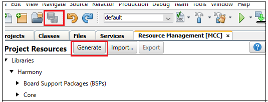
Save all and then click the Generate button. This will generate code for all the device resources that have been added in the project graph.
There is a library folder inside the PAC1934 generic library v1.2. In that folder, PAC193x.h and PAC193x.c files are available.
Add the PAC193x.h in header files and PAC193x.c in Source Files of the project.


Functions to be called from application to monitor power/current via I2C are as follows:
- PAC193x_Device_Initialize(): Initializes the PAC1934 device
- PAC193x_RefreshV(): This commands is used before reading the register of PAC1934
- PAC193x_GetVBUSn_mV(): To get the V_Bus voltage in millivolts
- PAC193x_GetVPOWERn_mW(): To get the V_Power voltage in milliwatts
- PAC193x_GetEnergy_mWh(): To get the Energy in milliwatt-hours
- PAC193x_GetISENSEn_AVG_mA(): To get the average current in milliamps
Refer to main.c for demo code.
Run the Harmony Application
Connect the J38 and J39 jumpers to SAM9X75, which will connect PAC1934 to SAM9X75. Refer to the Power measurement I2C connection PAC1934.

Connect the USB 2.0 Micro-B cable in J2 (USB_A) to power up the board.
Take a microSD card formatted with FAT32 file system.
Download the pre-built binaries and copy the boot.bin and harmony.bin files to the microSD card.
Insert the microSD card to J14 on the SAM9X75 Curiosity Development Board.
Perform a reset by pressing RESET button on the SAM9X75 Curiosity Development Board.
PAC1934 power monitoring can be done through SAM9X75 Curiosity Development Board using pre-built application.
Open the terminal to see the output.

Method 2 Summary
In Method 2, we learned how to create, configure, build, and run a project using the MPLAB Harmony v3 software framework within MPLAB X IDE. This method enables power consumption monitoring directly using the SAM9X75, eliminating the need for external software. Additionally, this approach allows for real-time integrated monitoring of power usage across various components, providing a streamlined and efficient solution for power analysis on the target hardware.
Results
The following results are recorded while running ROM BOOT without loading AT91 and MPLAB Harmony application.
| ROM BOOT | |||||
| VDDCORE (1.15V) | VDDIODDR (1.35V) | VDD_3V3 (3.3V) | |||
| 45 mA | 14.9 mW | 8 mA | 0.01W | 87 mA | 10.4 mW |
The following results are recorded while running AT91Bootstrap without the MPLAB Harmony application. AT91Bootstrap loaded from an SD card.
| AT91Bootstrap (SD Card) | |||||
| VDDCORE (1.15V) | VDDIODDR (1.35V) | VDD_3V3 (3.3V) | |||
| 40 mA | 13 mW | 8 mA | 0.0097W | 118 mA | 13.5 mW |
The following results are recorded while running MPLAB Harmony application with endless loop from JTAG.
| Clock Speed | Endless application with JTAG | |||||||
| CPU CLK (MHz) | MAIN SYSTEM BUS CLK (MHz) | DDRAM CLK (MHz) | VDDCORE (1.15V) | VDDIODDR (1.35V) | VDD_3V3 (3.3V) | |||
| 800 | 266 | 266 | 40 mA | 13 mW | 8 mA | 1.0 mW | 129 mA | 14.8 mW |
| 600 | 200 | 200 | 37 mA | 12.2 mW | 9 mA | 1.1 mW | 101.5 mA | 11.6 mW |
| 400 | 133 | 133 | 40 mA | 13 mW | 10 mA | 1.2 mW | 102 mA | 11.6 mW |
The following results are recorded while running the MPLAB Harmony application from JTAG.
| Clock Speed | Application (I2C + UART + JTAG) | |||||||
| CPU CLK (MHz) | MAIN SYSTEM BUS CLK (MHz) | DDRAM CLK (MHz) | VDDCORE (1.15V) | VDDIODDR (1.35V) | VDD_3V3 (3.3V) | |||
| 800 | 266 | 266 | 49.744 mA | 163.414 mW | 7.019 mA | 8.032 mW | 129.089 mA | 148.251 mW |
| 600 | 200 | 200 | 46.997 mA | 154.393 mW | 7.935 mA | 9.081 mW | 104.065 mA | 119.512 mW |
| 400 | 133 | 133 | 43.945 mA | 144.696 mW | 7.935 mA | 9.143 mW | 78.735 mA | 90.289 mW |
| Clock Speed | MIPI@60MHz | |||||||
| CPU CLK (MHz) | MAIN SYSTEM BUS CLK (MHz) | DDRAM CLK (MHz) | VDDCORE (1.15V) | VDDIODDR (1.35V) | VDD_3V3 (3.3V) | |||
| 800 | 266 | 266 | 59 mA | 19.5 mW | 9 mA | 10 mW | 185 mA | 21 mW |
| 600 | 200 | 200 | 45 mA | 14.5 mW | 8 mA | 8 mW | 112 mA | 12.5 mW |
| 400 | 133 | 133 | 40 mA | 13 mW | 8 mA | 8 mW | 110 mA | 12.5 mW |
Learn More
- SAM9X75 Curiosity Development Board - Introduction
- SAM9X75 Curiosity Development Board - Features
- SAM9X75 Curiosity LAN Kit - Quick Start Guide for Linux®
- SAM9X75 Curiosity LAN Kit - Quick Start Guide for MPLAB® Harmony v3
- SAM9X75 Curiosity Development Board - Booting Demo Linux® Image
- SAM9X75 Curiosity Development Board - Console Serial Communications